Automatic 4-channel pwm PC fan controller.
How to make “Automatic 4-channel quiet pwm PC fan controller.” With optional programmable RGB LED display.
Arduino 4-channel automatic fan controller with programmable RGB LED strip
I received an new Antec 902 case with tons of air flow but the unit came with these intensely bright blue LED 2-wire fans. These fans while not particularly loud themselves, were just noisy enough to force me to turn up my volume excessively when watching movies. This wasn’t considerate to the rest of the household as I’m the only nite-owl. Not to mention the ultra bright LEDs glaring over the movies of a darkened room, not cool.
So to remedy this I made a 4-channel automatic pwm fan controller using an Arduino UNO, LCD Smartie, Sensor Bridge (an add-on for LCD Smartie).
Here’s how I did it:
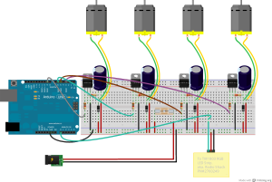
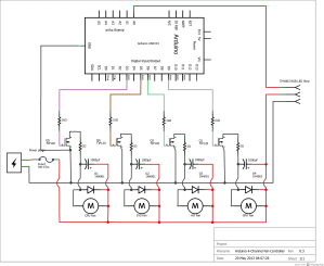
Novice Help: How to wire up a fan to be controlled by an Arduino.
Hardware:
You can grab the Fritzing file for this here.
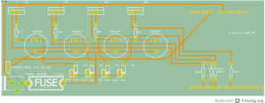
Or if you intend to make/order a PCB, snag the whole Fan Controller archive to get the Gerber files too.
Please note: The 2-Ohm resistors and the 1000mf capacitors are optional, but they really do help a LOT to make PWM’d fans quiet. You will need heat-sinks if you do include them. Alternatively, you can omit the 2-Ohm resistors and replace the TIP120’s with TIP31’s, for they have a higher internal resistance. However, all the heat dissipation will then depend entirely upon the heat-sink/air-flow.
For anyone that would like to know more about controlling 3 or 4-wire fans click here. Otherwise read on…
Software:
I use LCDsmartie to send data to my Arduino UNO via usbSerial link:
- Get/extract LCD Smartie (it just runs from the place you extracted it to).
- Get an add-on for it called “Sensor Bridge” extract it to the LCD Smartie/plugins/ folder. If it gives you trouble running it, just read the forum for advice.
- Inside LCD Smartie select the display plugin: testdriver.dll
- Set the COM port your Arduino uses. (Mine is COM5) ie, I use the init string of: COM5,115200,8,N,1
- Just to the left of the init string box there is a vertical tab called ‘Screen’, set the ‘LCD size’ to 1×40.
- Close the program. This frees the com port so we can upload the sketch.
Grab a copy of the sketch here.
Unzip it. There should be 3 files:
- SA4chanFCv4.ino – were the options are for you to play with.
- addLEDstrip.ino – this is an optional file for playing with programmable RGB LED light strips. (Colors and intensity are temperature responsive.)
- program.ino – the actual program that does the work.
Don’t want the LED stuff, its just junk to you? No, problem. Just throw it out! (delete the file)
Open the SA4chanFCv4.ino file in your Arduino IDE tweak as needed and upload.
Now lets get this show on the road.
Remember the folder that you extracted the SensorBridge.dll plugin into? Look at it again. Since we ran LCD Smartie once already, SensorBridge made a log file called SBReport.txt, the lines were interested in are the ones that start with ‘Command : ‘ followed by something like: $dll(SB,3,0,0.00) its these entries we need to use later.
Open it and you’ll see the list of the sensors it found in your PC. Will need this info later, so keep it open for now.
Almost done:
Fire up LCD Smartie again, this time lets put it to work…
The Arduino sketch indexes the numbers by using the preceding lowercase letter, records the data sent, then validates the end of entry by looking for the next alphabetical letter to cap it off. Then repeats until the serial buffer is empty.
In the setup screen under Screen settings in the long text box put, an lowercase a followed (no spaces anywhere) by one of those $dll(SB,#,#,0) entries, follow that with the subsequent lowercase letter, in this example its a b so a chain of these would look like:
a$dll(SB,3,0,0)bb$dll(SB,2,9,0)cc$dll(SB,2,10,0)dd$dll(SB,2,11,0)e
For me I used:
a$dll(SB,5,0,0)bb$dll(SB,3,9,0)cc$dll(SB,1,10,0)dd$dll(SB,1,11,0)ee$dll(SB,9,0,0)ff$dll(SB,9,2,0)gg$dll(SB,3,5,0)hh$dll(SB,3,6,0)ii$dll(SB,3,7,0)jj$dll(SB,3,8,0)k
My layout: aGPUtempbbCPUtempccVregTempddSysTempeeHD0TempffHD1TempggCore0TemphhCore1TempiiCore2TempjjCore3Tempk
That’s it. Hook up your fans. From here on out its just a matter of tweaking the sketch.
Although its easy to change, just remember; By default the Arduino sketch is looking for data in the order of GPUtemp, CPUtemp, VregTemp, SysTemp, HD0Temp, HD1Temp, Core0Temp, Core1Temp, Core2Temp and Core3Temp.


would this layout work if i were to use n-channel mosfets as well?
Yes they can.
For example the IRLB8721 mosfet (hexfet) would be a great choice, just omit the 1Kohm resistors and drive them directly from the arduino output pins. Just be sure to use some 10watt 2.2-Ohm power resistors to soften up the power going into the caps.
You can find some here: http://www.adafruit.com/products/355
Hello.
How would a sketch need to look like when to channel 20 of these PC fans?
I am new to this.
Any help would be wonderful.
Best
FW
Hmm, 20 fans you say? Wow that’s epic!
There is some hidden problems with your request though:
2. If you need *all* 20 fans to be variable speed your going to face some additional challenges…
The actual problem is that an Arduino has only so many PWM channels to offer. For example, the Arduino model Mega2560 has the most PWM channels but, still it only has 15.
For the last five pins you can:
b. Use a PCA9685 i2c chip that allows you to add +16 pwm channels per chip (62 chips max). But you’ll need to do your own code for it. Most complex ‘over the top’ method. Lots of coding.
c. Fake it with softPwm library to bit bang those last five on/off fairly rapidly. Mildly complex, light coding required.
d. Slave them into 5 other fan channels. (Make a 15 channel controller with 5 of those as dual-fan outputs) Easy, ‘pimp my stock Arduino’ method.
e. Wire 5 fans per transistor (INCLUDE A HEATSINK), use stock 4-channel code. Easiest, ‘Bubba fix’d it’ method.
Ok, on to the software stuff…
Well, first take a look at the setup options for LCD Smartie. Under “Display settings” you’ll see a tab labeled “Screen”… change the drop down from “1×40” to “2×40” Add in another 10 sensor entries using the same
letter sensorOutput nextLetterscheme, just be sure to start where the first line leaves of at.Then in the arduino code you would need to change every line that has
[11]in it to[21]. Then add in ten more values between the{}braces of each one you modify. Changepin[7]topin[21]and replace the values with the 20 pins your going to use for each fan.Optional:
By default the sketch looks for 4 fans to kick on while waiting for data; to change this behavior replace
pinBootup[5]withpinBootup[20]and also replace the values with your fan output pins, only this time place the entries in the order you want to see them boot-up in.Afterwards, click on the tab labeled “program” and under
void setup()find the line:for(int i=0;i<4;i++){replace with:
for(int i=0;i<20;i++){This will allow the controller to boot all 20 fans fading them in from 0~pwmMax per fan sequentially upon bootup. NOTE: That’s a lot of waiting so several lines below it you see
delay(stepDelay);change it todelay(stepDelay/5);if you want a faster boot sequence.Hello dewy721,
I see that I need to go into details.
Thank you very much for your answer.
Well, this is for an artistic installation, where the 20 fans blow up fixed paperstripes.
So it is not for any pc cooling.
I also do not need the LED/LCD Smartie stuff.
The 20 fans also shouldn’t be controlled individually by 20 PWMs.
They should run synchron on the same power level.
Well, I am really new to Arduino.
What I do is researching possible ways of solving this task for me.
I spotted the information that one Arduino PWM should be enough to send
the signal to the fans because each fan has got an inbuild PWM pin.
These fans should react to a „HC-SR04 ultrasonic range finder“: the closer the person is in front of the fans the faster they should run.
—-
this is fan-type i want to use
Link: http://www.conrad.de/ce/de/product/871001/LogiLink-8-cm-PC-Luefter
12V DC
0,14A
4 pins
——
I have yours and another persons tutorial/sketch which I hoped to understand and join togehter to have my soltuion.
This person here controlls LEDs with the „HCR-SR04“.
Link: http://fritzing.org/projects/hc-sr04-and-led-project
Combining your way and this person’s way should be a solution I hoped.
Are you interested in helping me out to create the technical backbone for my project?
My major work for this project is the conceptual part and the designing part.
For the fan controlling part I really need some help.
It would be wonderful if you would help me out on this.
Best,
FW
Try this instead. I found an example at https://gist.github.com/flakas/3294829 that looks to be more useful for you.
I’ve modified the example below to do exactly what you asked. That is, control 20 fans from one transistor using the SR04 ping transducer for input.
I hope it helps. 🙂
Thank you so much.
I will give it a try as soon as possible.
Thank you.
FW
Pingback: Anonymous
I have a question about the 2ohm resistors. Can i use 1/4W resisistors here or do I need some that can handle more W?
And you say you need heatsink if you use the 1000µF capacitor and 2ohm reisistor, exactly what needs to be heat sinked?
I’d recommend 5watt or bigger if you plan to use TIP120’s. (Or use smaller/no caps and get a little more noise.) Reason being is that the transistor is (for a microsecond or two) short circuited via the capacitor. If want to you use lossy TIP31’s like I did then the transistors become the resistor as well. Then you can skip the 5w resistors, but you WILL NEED a heat sink for the transistors. I salvaged a PSU heatsink and put the circuit in direct airflow. It works a treat for me at least.
NOTE: This circuit make the most heat when the fans run slow, as the fans would be relying mostly on stored capacitor power (slow PWM). Then the heavily drained caps pull more current (when it can) to fill back up.
Okay, thank you very much!
Great project, cant wait to get a quiet PC
Can you use an arduino motor shield with this setup?
I don’t why you couldn’t use the motor shield but it would only provide output for two fan channels. You’d just need to change the pin settings to point to the motor shield’s pwm pins. Just set the ‘brake’, enable, direction pins to either high or low (I dont remember which atm.)
Awesome, although I like your setup better, I’m going to evaluate both.
On a side note, what does the unit use for measuring temperature? Or did I miss that in the write up?
Unfortunately the sensor bridge .dll supports only one temperature scale, Celsius.
Ok but the breadboard setup will work well for connecting several PWM fans, then I just need to work out the code correct?
Correct. Alternately, this project is a good candidate for using a proto-shield. It should fit nicely on one.
Well, I’ll have to do a lot more research…I thought it would be a lot easier to implement a DS18B20 and a PWM fan together. My lack of PWM / Arduino knowledge is killing me now..ugh!
Believe me, I know how you feel. <:)
At the moment I'm eyeball deep, cross-referencing 7 different knowledge articles on: 3 LinuxCNC configuration guides, 2 BeagleBone Black hardware reference manuals, and 1 MachineKit setup example and finally a spreadsheet regarding one of several PRU LinuxCNC-HAL driver modules on a microcontroller platform I just received 2 weeks ago.
If your willing to take a few Baby steps. Its all the courage you'll really ever need.
Could you please share the Sensor Bridge add-on? The link provided is down. Thanks!
Pingback: Automatic 4-channel pwm PC fan controller. | basheerabdulwahab
Hi, thanks for all the great info.
Just wondering, what PWM frequency is this running at? I couldn’t work out from your code, but I read that the default PWM freq for the Arduino using analogWrite is 980Hz, much too low to be out of audible range.
Do you think it would be quiet if I ran an n-channel mosfet using PWM at over 25kHz, even with the capacitors/resistors omitted?
Also, just a small correction: where you said, “Please note: The 2-Ohm resistors and the 1000mf capacitors are optional”, I think you meant to say “1000uF capacitors”.
Thanks again.
Yes, you can change the pwm frequency, just be mindful that (if I recall correctly) timer0 is also used by micros() & millis() which is used for the LED code & serial library.
Also, the 3 different timers are hardwired to specific pins as well. So while you can do it, you’ll have to accomodate those details into the build as well.
Here’s a cheatsheet on the subject….
http://playground.arduino.cc/Main/TimerPWMCheatsheet
Happy hacking.
Thanks. Do you think the noise will be lowered by making the PWM much faster? I will test it if you don’t know.
I have a project where I want to use all the PWM outputs of a Arduino Due (12) for controlling 12 fans. I guess it is possible to use the same electronics. Just make them 12 instead of 4?
And what about this:
“The 2-Ohm resistors and the 1000mf capacitors are optional, but they really do help a LOT to make PWM’d fans quiet. You will need heat-sinks if you do include them”
For me it is important to make them as quiet as possible. How and where do I place the heatsink? Next to the capacitor?